Dear Nektar++ forum,
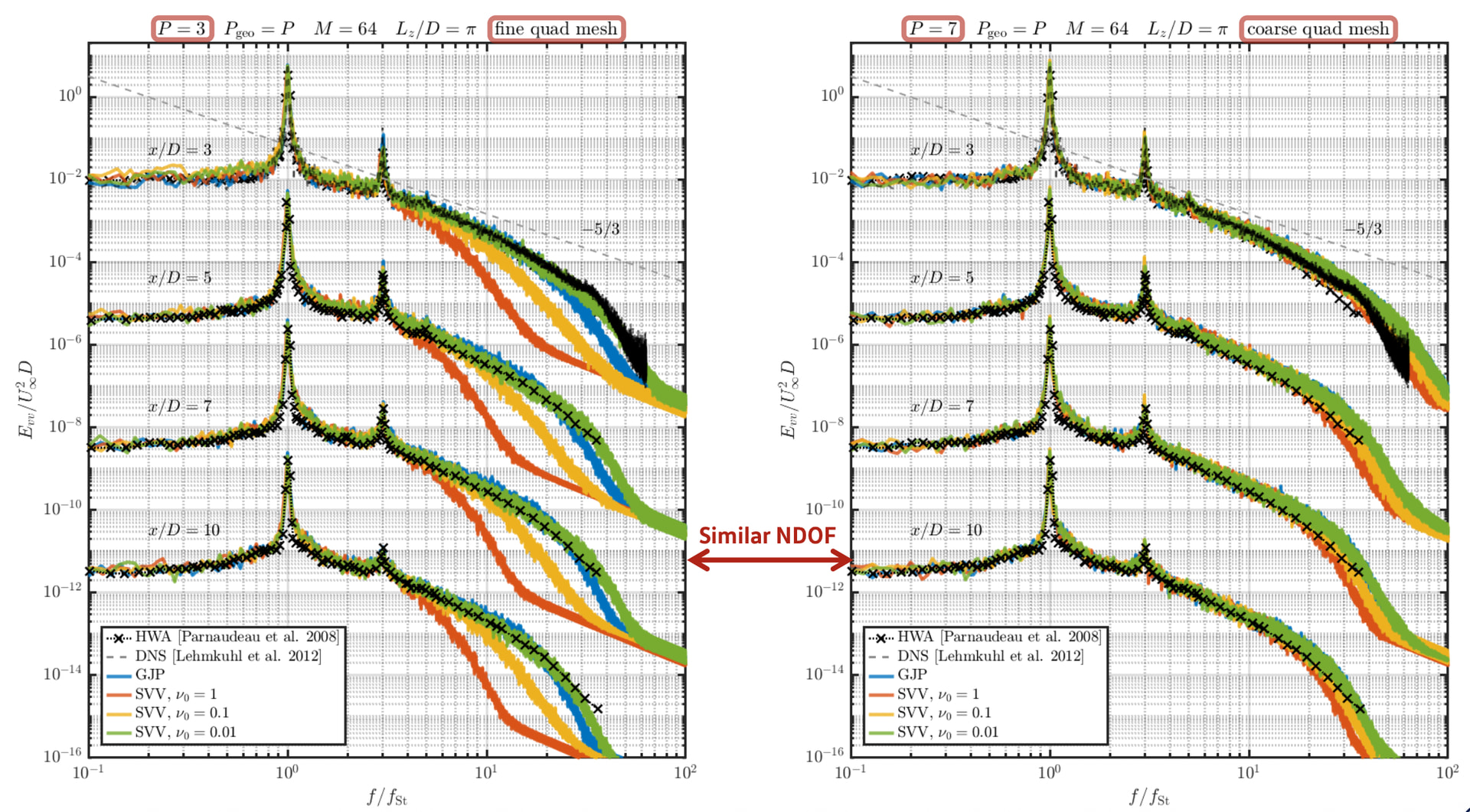
I am trying to reproduce the experimental turbulent boundary and have been encountering some issues with Synthetic Turbulence decaying downstream. I was wondering if anyone attempted to use this for a different case to the paper Isler et al. (2025) and would really appreciate any advice for the correct implementations.
I am using a structured mesh for this and I impose a mean turbulent boundary-layer velocity profile at the inlet fitted directly to the experimental data, and I use SEM to introduce turbulent fluctuations with the aim of sustaining this boundary layer as it develops downstream.
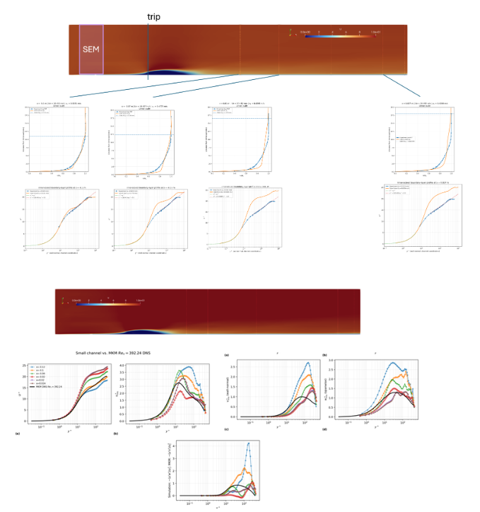
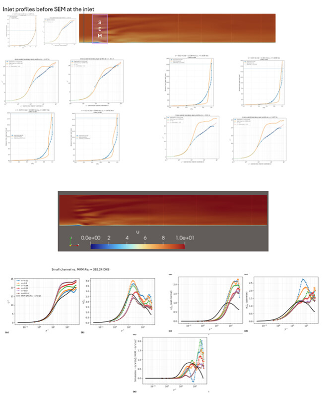
Although the inlet mean profile is already representative of the experimental turbulent boundary layer, the turbulence decays progressively downstream and mean velocity profiles move away from desired profile and becomes more laminar.
Another interesting detail is, when I plot the re stresses downstream of the trip or SEM, I observe a partial convergence towards the DNS Reynolds stresses (varies with uu,vv,ww) I used for SEM implementation, however mean boundary layer profile drifts from the turbulent state.
I have tested synthetic turbulence, an immersed-boundary trip using the Smoothed Profile Method (SPM) and both together. The combined SEM + SPM approach gives the closest agreement with the experimental mean velocity profile initially, but the fluctuations still decay further downstream and I have not yet obtained a sustained turbulent boundary layer over the required development length.
Current setup details:
- Incompressible Velocity Correction Scheme with SPM → Trip
- Incompressible Velocity Correction Scheme-> SEM
- P=2 (NUMMODES=3)
- IMEX, order 2
- Time step = 1x10^-5 s
- U_inf=10 m/s
- nu=1.49x10^-5 m²/s
- No-slip lower wall
- Free-slip upper boundary
- Spanwise-periodic boundaries
- Channel height = 38.75 mm
- Span = 46.5 mm
- Length= 261 mm
- Trip-wire radius = 3 mm, with its centre 1 mm below the wall, giving a 2 mm exposed height, has 2 spanwise wavelengths to break the symmetry across the span
- SPM smoothing thickness = 0.25 mm
- Spectral vanishing viscosity: DGKernel
- Spectral/hp dealiasing enabled
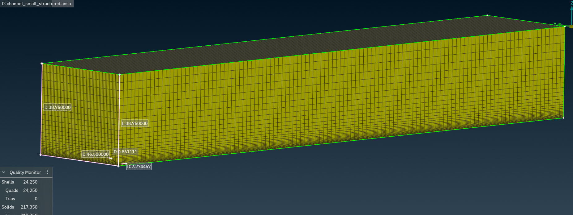
DOF= 5.8M @P2
My wall resolution for these cases resulted u_tau ~ 0.5 m/s, and appx. wall-unit resolution, note x, y and z are streamwise, spanwise and wall-normal resp.:
| wall resolution | |
|---|---|
| Streamwise spacing, x+ | 30 |
| Spanwise spacing, y+ | 10 |
| First wall-normal point, z+ | 0.458 |
These wall units are based on wall-averaged quantities / time-averaged over approximately two through flows based on domain length.
Synthetic turbulence strategy
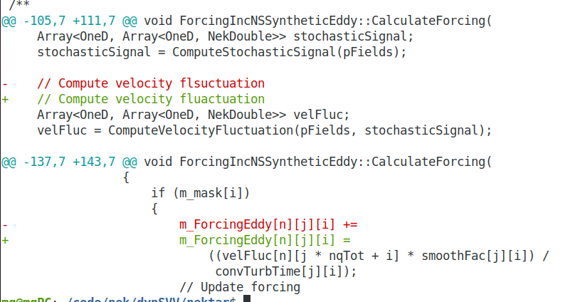
I have used Isler et al. (2025) as a reference for the source-term-based synthetic turbulence implementation and mainly followed the channel validation example. Below is a short summary of the Re stresses I used for SEM implementation.
Tests:
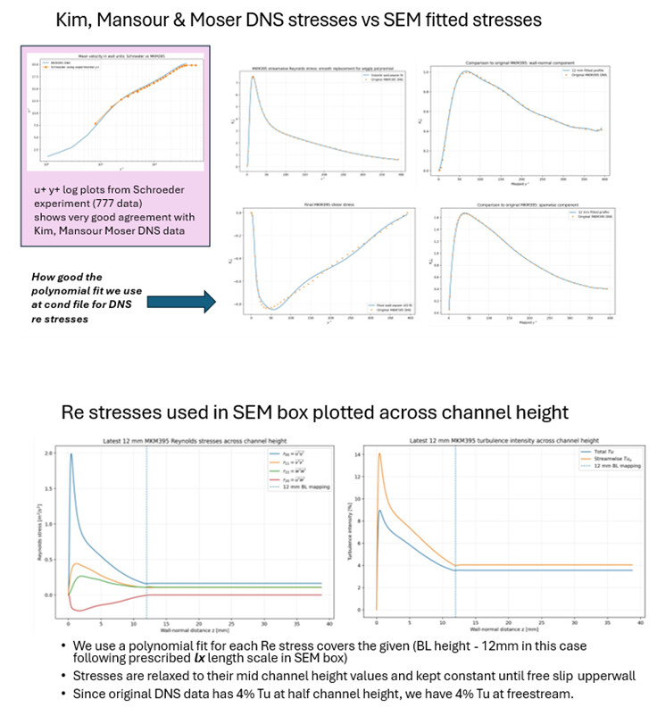
A. Reynolds stresses: I have tested profiles based on the Moser, Kim and Mansour Re_tau=395 channel DNS, mapped to the experimental boundary-layer thickness and to my coordinate system (Fig2). I have also tested simpler diagonal/isotropic stress tensors and profiles that approach prescribed free-stream turbulence levels.
B. Length scales: I have tested several anisotropic characteristic length-scale combinations. I mainly used 1.2x turbulent boundary layer height(following the paper again Isler et al. (2025)) and slightly increased in one case, the streamwise characteristic scale as 1.5 TBL height. Increasing or decreasing these scales has not clearly improved the downstream persistence of the turbulence.
Example 1.2 TBL height length scale scaling:

C. Turbulence intensity: I have varied the imposed turbulence intensity and the outer stress levels but have not observed a clear improvement in the downstream decay.
**Example provided Re stresses (Case3 below)
**
(plots available from link at the end of post link)
SEM + SPM gives the best agreement with the experimental mean profile. However, neither approach has yet produced turbulent fluctuations that remain sustained over the required downstream distance.
Mid-span time-averaged boundary layer profiles (linear &log) & Reynold Stresses:
Case1-Trip case with IBM + SEM:
Case3-SEM only using Kim, Moser Mansour DNS Channel data:
I suspected damping might effect the turbulence state downstream. There appears to be a strong sensitivity to spectral vanishing viscosity values, where even a tiny reduction in SVV parameters (currently using DG Kernel) makes the calculations diverge and SVV is not used in the above paper Isler et al. (2025).
I thought about implicit velocity correction scheme to maybe allow a larger CFL decreasing SVV but using this is not compatible with the SPM implementation (case3 where I got the closest profile to experiment). I had some trouble with my previous attempts to use this scheme for the type of cases with instantaneous divergence behaviour, which resulted in running but frozen flow fields. I am able to progressively decrease SVV for other set-ups (777 film cooling case) so I wondered whether there is a way to reduce in a stable way.
To my understanding I should be able to use only SEM and able to generate enough turbulence, so I would be very happy to have any suggestions what would be the most important checks.
My main points/questions are:
- My wall resolution mainly matches with the Isler et al. (2025)
- Is there a recommended diagnostic in Nektar++ for determining whether DGKernel SVV is removing a significant fraction of the turbulent fluctuations?
- From the Isler et al. (2025) 5 delta(channel half height) should give a positive trend for converging the required boundary layer profile but maybe more development length is required? I have extracted profiles from 1-15 delta downstream.
I included more detailed information alongside some example xml condition files I have been using below hopefully would also be useful for people would like to use the method.
Synthetic Eddy Method Implementation tests using Nektar++.pptx
Any general recommendations to understand the root cause of the lack of turbulence downstream would be very valuable.
Thank you very much for your help!